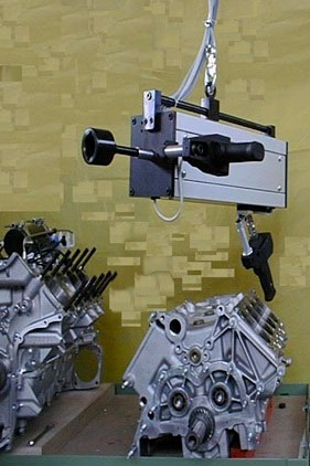
The system was conceived to control the rolling torque (or free rotation) of a combustion engine.
The system was conceived to control the rolling torque (or free rotation) of a combustion engine.
During the test, the torque is plotted, in real time, with reference to the angle and the elapsed time. Subsequently, the values of the parameters of the entire graph resulting from the test are processed to evaluate even small interferences, within the predetermined range of free rotation, due to excessive friction and spurious mechanical oscillations. The system is also suitable to other applications, for example to the "wheel hub", where the verification of the free rotation is fundamental for the acceptance of the workpiece under test.
The predetermined range of free rotation is previously determined in the investigation phase of the best suited parameters based on a few samples that were considered definitely optimal. The analysis of the parameters graph for torque/time/angle is a valuable help to determine the most appropriate strategy and parameters. The operator defines such a strategy by setting the working window in relation to a certain value of Y-axis (torque) with respect to an observation range on the X axis (time or angle).
By controlling the above mentioned parameters, the SPM100 RTC control system is able to discriminate the possible breakage and/or wear of the tools under measure and the deformation of the assembled materials.
The control unit automatically performs the storage of all the torque values measured and the results obtained.
Sequence of the control phases
To start the control cycle it is necessary, first of all, to select the group of production (GP) for the type of engine under test and set its code number; only after these two commands, the tool is enabled to carry out the cycle control with the parameters set for the selected engine. When the transducer detects a torque value higher than the preset 'Ms' threshold, the control unit starts recording the torque, detected by the transducer, and the angle of rotation, determined by the encoder embedded into the tool, until the end of the cycle. At the tool stop, the control ends the reading cycle and compares the value of the maximum torque, the average value of the torque, the value of the rotation angle and the time elapsed.
The stop of the tool can be programmed in two ways: when the angle value reaches the value of 'AP' (boundary in angle) or when the rotation time exceeds the value of 'TP' (boundary in torque).
If the measured data are within the preset tolerances it is reported that the rolling torque is good, otherwise, if they are outside the limits, the discard is pointed out.
These data are sent to a line printer and a Host Computer for filing.
Options
- Remote keypad for programming
- GP Box selector with electric enabling key
- Light array device reporting Pass/Fail/End cycle buzzer
- External solenoid valve control for marking or pallet evacuation with programmable time 0-20 sec. or other desired functions
- Barcode device reader
- Customized prints
- Customized statistical reports
- No. of single cycles or overall cycles
- No. of upper/lower limit fails
- Cp, CpK, Cm, CmK
- Sigma